Overview
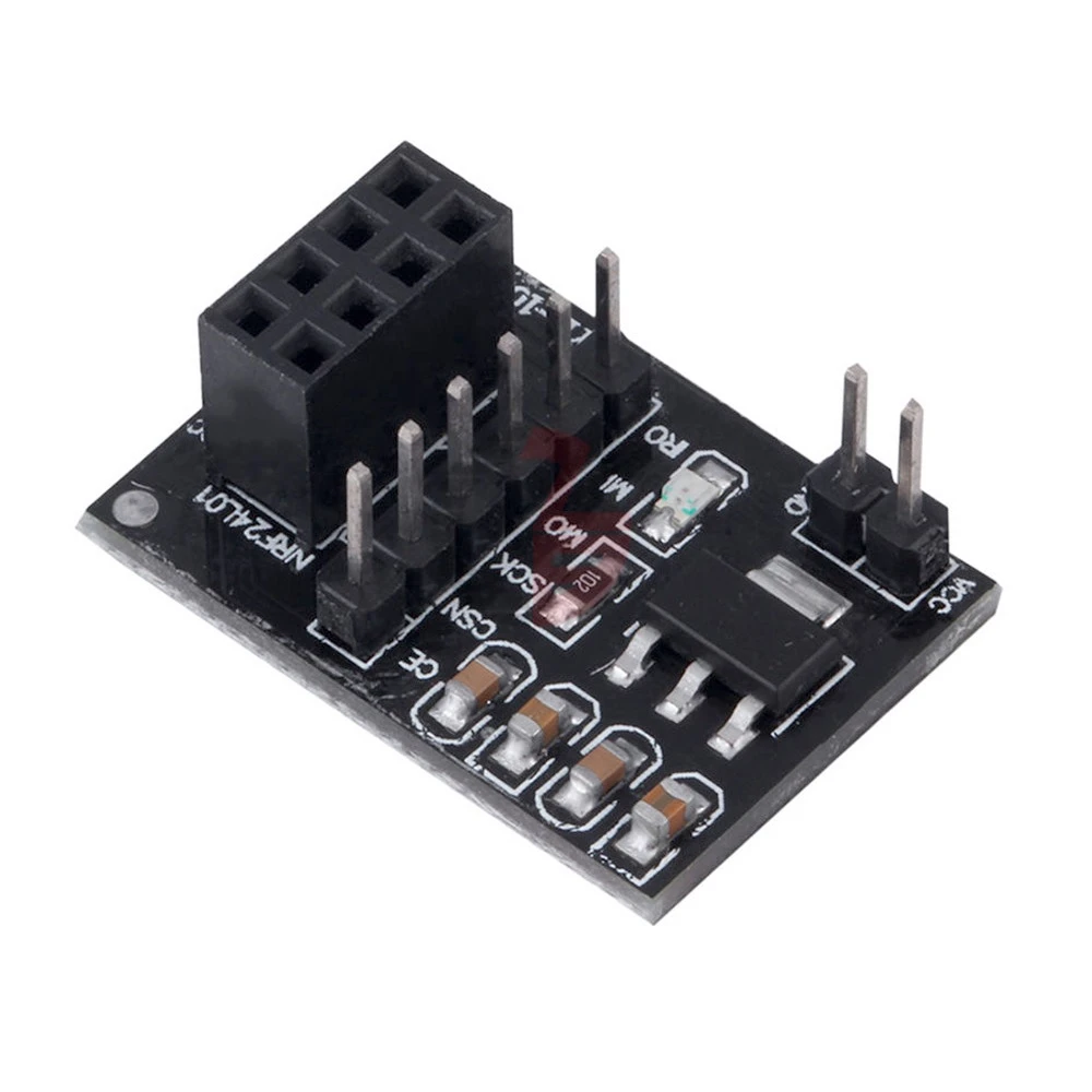
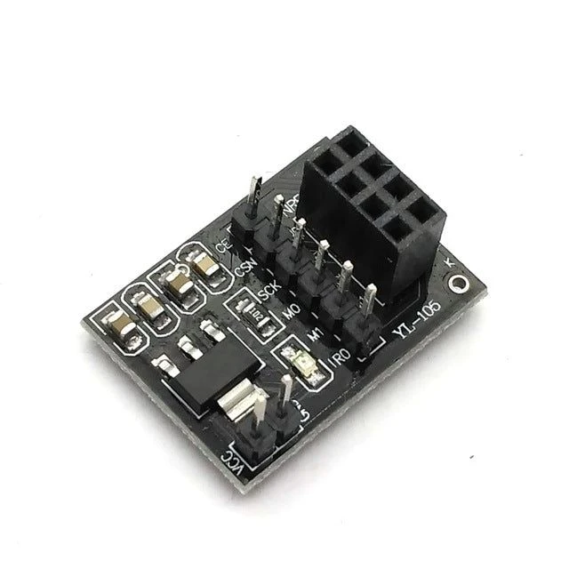
The NRF24L01 Adapter Board is designed to simplify the connection of the NRF24L01 2.4 GHz wireless transceiver module to microcontrollers. It provides voltage regulation, level shifting, and a standard pin layout, allowing the NRF24L01 to operate safely at 3.3 V even when powered from a 5 V system like Arduino.
Key Features
Provides stable 3.3 V supply for the NRF24L01
Supports 5 V logic level conversion from Arduino or other 5 V microcontrollers
Compatible with Arduino, ESP8266, ESP32, STM32
Standard GND, VCC, CE, CSN, SCK, MOSI, MISO, IRQ pin layout
Includes filter capacitors for voltage stabilization
Breadboard-friendly or stackable with modules
Technical Specifications
| Parameter | Specification |
|---|---|
| Input Voltage | 3.3–5 V DC |
| Output Voltage | 3.3 V stabilized for NRF24L01 |
| Logic Level | 5 V tolerant inputs (level-shifted to 3.3 V) |
| Power Supply | Onboard LDO voltage regulator + filter capacitors |
| SPI Interface | CE, CSN, SCK, MOSI, MISO |
| Indicator | Optional power LED on some boards |
| Dimensions | ~24 × 16 mm (typical) |
| Pin | Function |
|---|---|
| VCC | 3.3 V stabilized output for NRF24L01 |
| GND | Ground |
| CE | Chip Enable (connects to microcontroller GPIO) |
| CSN | SPI Chip Select |
| SCK | SPI Clock |
| MOSI | SPI Master Out |
| MISO | SPI Master In |
| IRQ | Optional interrupt line |
| 5 V / Vin | Input from microcontroller or USB |
Applications
Easily connect NRF24L01 modules to Arduino, ESP8266, or ESP32
Wireless sensor networks
Robotics and remote control projects
STEM labs for learning wireless communication
IoT prototypes with multiple nodes
No review given yet!
You need to login to view this feature
This address will be removed from this list